|
|
|
|
| 전자카운터 |
|
|
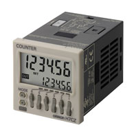
H7CZ
(생산중지예정 2022-03-31)
|
|
|
|
|
|
|
편리한 사용에 "경제성"을 플러스!
2022 년 03 월 수주 종료 예정
|
|
|
|
|
|
|
|
|
|
|
|
|
|
|
|
|
|
| Service Info |
 |
대체상품보기 |
|
|
대체상품이 존재하지 않습니다.
|
|
|
|
|
|
|
Ratings
| Models |
H7CZ-L8 |
H7CZ-L8D1 |
| Configuration |
1-stage preset counter |
| Ratings |
Power supply voltage *1 |
100 to 240 VAC, 50/60 Hz |
24 VAC, 50/60 Hz or 12 to 24 VDC |
Operating voltage
fluctuation range |
85% to 110% of rated supply voltage (12 to 24 VDC: 90% to 110%) |
| Power consumption |
Approx. 9.4 VA at 100 to 240 VAC, Approx. 7.2 VA/4.7 W at 24 VAC/12 to 24 VDC, Approx. 3.7
W at 12 to 24 VDC |
| Mounting method |
Flush mounting or surface mounting |
| External connections |
8-pin socket |
| Degree of protection |
IEC IP66, UL508 Type 4X (indoors) for panel surface only and only when Y92S-29 Waterproof
Packing is used. |
| Input signals |
Count, Reset |
| Counter |
Maximum counting speed |
30 Hz or 5 kHz (switchable) (ON/OFF ratio 1:1) *2 |
| Input mode |
Increment, Decrement |
| Output mode |
N, F, C, R, K-1, P, and Q. |
| One-shot output time |
0.01 to 99.99 s |
| Reset system |
External (minimum reset signal width: 1 ms or 20 ms, selectable), Manual, and Automatic reset
(internal according to C, R, P, and Q mode operation) |
| Prescaling function |
Yes (0.001 to 99.999) |
| Decimal point adjustment |
Yes (rightmost 3 digits) |
| Sensor waiting time |
290 ms max. (Control output is turned OFF and no input is accepted during sensor waiting time.) |
| Input method |
No-voltage inputs:
ON impedance: 1 kΩ max. (Leakage current: 12 mA at 0 Ω)
ON residual voltage: 3 V max.
OFF impedance: 100 kΩ min. |
| Control output |
3 A at 250 VAC/30 VDC, resistive load (cosΦ =1), Minimum applied load: 10 mA at 5 VDC (failure
level: P, reference value) |
| Display *3 |
LCD
Character height
Count value: 10 mm
Set value: 6 mm |
| Digits |
6 digits
-99999 to 999999
(-5 digits to +6 digits) |
| Memory backup |
EEPROM (overwrites: 100,000 times min.) that can store data for 10 years min. |
| Operating temperature range |
-10 to 55°C (-10 to 50°C if Counters are mounted side by side) (with no icing or condensation) |
| Storage temperature range |
-25 to 70°C (with no icing or condensation) |
| Operating humidity range |
25% to 85% |
| Front panel color |
Light gray (5Y7/1) |
*1.Do not use the output from an inverter as the power supply.The ripple must be 20% maximum for DC power.
*2.A response of 10 kHz is possible if the response speed is 5 kHz and the 1-stage preset counter input mode is increment or decrement.
*3.The display is lit only when the power is ON. Nothing is displayed when power is OFF.
Characteristics
| Insulation resistance |
100 MΩ min. (at 500 VDC) between current-carrying terminals and exposed non-current-carrying metal parts,
and between non-continuous contacts |
| Dielectric strength |
2,000 VAC, 50/60 Hz for 1 min between current-carrying metal parts and non-current-carrying metal parts
2,000 VAC, 50/60 Hz for 1 min between power supply and input circuit (1,000 VAC for 24 VAC/12 to 24 VDC)
1,000 VAC, 50/60 Hz for 1 min between control output, power supply, and input circuit (2,000 VAC)
1,000 VAC, 50/60 Hz for 1 min between non-continuous contacts |
| Impulse withstand voltage |
3.0 kV between power terminals (1.0 kV for models with 24 VAC/12 to 24 VDC)
4.5 kV between current-carrying terminals and exposed non-current-carrying metal parts (1.5 kV for models
with 24 VAC/12 to 24 VDC) |
| Noise immunity |
±1.5 kV between power terminals
±600 V between input terminals
Square-wave noise by noise simulator (pulse width: 100 ns/1 μs, 1-ns rise) |
| Static immunity |
Malfunction: 8 kV
Destruction: 15 kV |
Vibration
resistance |
Destruction |
10 to 55 Hz with 0.75-mm single amplitude each in three directions for 2 h each |
| Malfunction |
10 to 55 Hz with 0.35-mm single amplitude each in three directions for 10 min each |
Shock
resistance |
Destruction |
300 m/s2 each in three directions |
| Malfunction |
100 m/s2 each in three directions |
| Life expectancy |
Mechanical: 10,000,000 operations min.
Electrical: 100,000 operations min. (3 A at 250 VAC, resistive load, ambient temperature condition: 23°C)* |
| Weight |
Approx. 100 g (Counter only) |
*Refer to the Life-test Curve.
Life-test Curve (Reference Values)
A current of 0.15 A max. can be switched at 125 VDC (cosφ=1) and current of 0.1 A max. can be switched if L/R=7 ms. In both cases, a life of 100,000 operations can be expected.
Using as a Counter *1
| Inputs |
Count |
Reads counting signals.
Increment and decrement inputs accepted. |
| Reset |
Resets present value and outputs. *2
Counting cannot be performed during reset input.
Reset indicator is lit while reset input is ON. |
| Outputs |
OUT |
Outputs signals according to the specified output mode when a set value is reached. |
*1.For information on operation of I/O functions, refer to Data Sheet.
*2.In elapsed time mode, the present value returns to 0; in remaining time mode, the present value returns to the set value.
The following table shows the delay from when the reset signal is input until the output is turned OFF. (Reference values)
| Minimum reset signal width |
Output delay time |
| 1 ms |
0.8 to 1.2 ms |
| 20 ms |
15 to 25 ms |
Caution: In the interenst of product improvement, specifications are subject to change without notice.
|
|
|
|
|
|