|
|
|
|
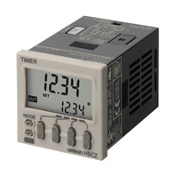
| 디지털 타이머 |
|
|
H5CZ
(생산중지예정 2025-03-31)
|
|
|
|
|
|
|
편리한 사용에 "경제성"을 플러스!
2025년 3월 수주 종료 예정
|
|
|
|
|
|
|
|
|
|
|
|
|
|
|
|
|
|
| Service Info |
 |
대체상품보기 |
|
|
대체상품이 존재하지 않습니다.
|
|
|
|
|
|
|
Ratings
| Models |
H5CZ-L8[] |
| Ratings |
Power supply voltage *1 |
100 to 240 VAC 50/60 Hz
12 to 24 VDC/24 VAC 50/60 Hz |
Operating voltage
fluctuation range |
85% to 110% of rated supply voltage (90% to 110% at 12 to 24 VDC) |
| Power consumption |
Approx. 6.2 VA at 100 to 240 VAC, Approx. 5.1 VA/2.4 W at 24 VAC/12 to 24 VDC *2 |
| Mounting method |
Flush mounting, Surface mounting, DIN track mounting |
| External connections |
8-pin socket |
| Degree of protection |
IEC IP66, UL508 Type 4X (indoors) for panel surface only and when Y92S-29 Waterproof Packing is used 4 digits |
| Digits |
| Time ranges |
0.001 s to 9.999 s, 0.01 s to 99.99 s, 0.1 s to 999.9 s, 1 s to 9999 s, 1 s to 99 min 59 s
0.1 m to 999.9 min, 1 min to 9999 min, 1 min to 99 h 59 min, 0.1 h to 999.9 h, 1 h to 9999 h |
| Timer mode |
Elapsed time (Up), Remaining time (Down) (selectable) |
| Inputs |
Input signals |
Signal, Reset
(no inputs on models with instantaneous contact outputs) |
| Input method |
No-voltage Input
ON impedance: 1 kΩ max. (Leakage current: 12 mA when 0 Ω )
ON residual voltage: 3 V max.
OFF impedance: 100 kΩ min. |
| Signal, reset |
Minimum input signal width: 1 or 20 ms (selectable, same for all input) |
| Reset system |
Power reset (depending on output mode), External reset, Manual reset, Automatic reset (depending
on output mode) |
| Power reset |
Minimum power-opening time: 0.5 s (except for A-3, b-1, F, ton-1, and toff-1 mode) |
| Reset voltage |
10% max. of rated supply voltage |
| Sensor waiting time |
250 ms max. (Control output is turned OFF and no input is accepted during sensor waiting time.) |
| Output |
Output modes |
A: Signal ON Delay I, A-1: Signal ON Delay II, A-2:
Power ON Delay I, A-3: Power ON Delay II, b:
Repeat Cycle 1, b-1: Repeat Cycle 2, d: Signal
OFF Delay, E: Interval, F: Cumulative, Z: ON/OFF-
duty-adjustable flicker, S: Stopwatch, toff: Flicker
OFF Start 1, ton: Flicker ON Start 1, toff-1:
Flicker OFF Start 2, ton-1: Flicker ON Start 2 |
|
Models with Instantaneous Contact Outputs
A-2: Power ON Delay I, b: Repeat Cycle 1,
E: Interval, Z: ON/OFF-duty-adjustable flicker,
toff: Flicker OFF Start 1, ton: Flicker ON Start 1 |
| One-shot output time |
0.01 to 99.99 s |
| Control output |
5 A at 250 VAC/30 VDC, resistive load (cos =1)
Minimum applied load: 10 mA at 5 VDC (failure level: P, reference value) |
| Display method *3 |
LCD; Present value: 10-mm-high characters
Set value: 6-mm-high characters |
| Memory backup |
EEPROM (overwrites: 100,000 times min.) that can store data for 10 years min. |
| Operating temperature range |
-10 to 55°C (-10 to 50°C if counters are mounted side by side) (with no icing or condensation) |
| Storage temperature range |
-25 to 70°C (with no icing or condensation) |
| Operating humidity range |
25% to 85% |
| Front panel color |
Light gray (5Y7/1) |
*1.Do not use the output from an inverter as the power supply. The ripple must be 20% maximum for DC power.
*2.Inrush current will flow for a short time when the power supply is turned ON.
Inrush Current (Reference Values)
| Voltage |
Applied voltage |
Inrush current (peak value) |
Time |
| 100 to 240 VAC |
264 VAC |
5.3 A |
0.4 ms |
| 12 to 24 VDC/24 VAC |
26.4 VAC |
6.4 A |
1.4 ms |
| 26.4 VDC |
4.4 A |
1.7 ms |
*3.The display is lit only when the power is ON. Nothing is displayed when power is OFF.
Characteristics
Accuracy of operating time and
setting error (including
temperature and voltage influences) |
Power-ON start: ±0.01% ±50 ms max. (See note)
Signal start: ±0.005%±0.03 ms max. (See note)
If the set value is within the sensor waiting time at startup the control output of the H5CZ will
not turn ON until the sensor waiting time passes.
Note: The values are based on the set value. |
| Insulation resistance |
100 MΩ min. (at 500 VDC) between current-carrying terminal and exposed non-current-
carrying metal parts, and between non-continuous contacts |
| Dielectric strength |
2,000 VAC, 50/60 Hz for 1 min between current-carrying metal parts and non-current-
carrying metal parts
2,000 VAC, 50/60 Hz for 1 min between power supply and input circuits for all models except
H5CZ-[]D
2,000 VAC, 50/60 Hz for 1 min between control output, power supply, and input circuits
1,000 VAC, 50/60 Hz for 1 min between non-continuous contacts |
| Impulse withstand voltage |
3 kV (between power terminals) for 100 to 240 VAC, 1 kV for 24 VAC/12 to 24 VDC
4.5 kV (between current-carrying terminal and exposed non-current-carrying metal parts) for
100 to 240 VAC 1.5 kV for 24 VAC/12 to 24 VDC |
| Noise immunity |
±1.5 kV (between power terminals) and ±600 V (between input terminals), square-wave noise
by noise simulator (pulse width: 100 ns/ 1 μs, 1-ns rise) |
| Static immunity |
Malfunction: 8 kV
Destruction: 15 kV |
| Vibration resistance |
Destruction |
10 to 55 Hz with 0.75-mm single amplitude each in three directions for 2 h each |
| Malfunction |
10 to 55 Hz with 0.35-mm single amplitude each in three directions for 10 min each |
| Shock resistance |
Destruction |
300 m/s2 in three directions, three cycles |
| Malfunction |
100 m/s2 in three directions, three cycles |
| Life expectancy |
Mechanical |
10,000,000 operations min. (under no load at 18,000 operations/h and ambient temperature of
23°C) |
| Electrical |
100,000 operations min. (5 A at 250 VAC, resistive load at 1,800 operations/h and ambient
temperature of 23°C) * |
| Weight |
Approx. 105 g (Timer only) |
*Refer to Life-test Curve.
Life-test Curve (Reference Values)
A maximum current of 0.15 A can be switched at 125 VDC (cosφ =1) and a maximum current of 0.1 A can be switched if L/R is 7 ms. In both cases, a life of 100,000 operations can be expected.
I/O Functions
For details, refer to the timing charts on Data Sheet.
| Inputs * |
Start signal |
Normally functions to start timing.
In modes A-2 and A-3, disable timing. In mode S, starts and stops timing. |
| Reset |
Resets present value. (In elapsed time mode, the present value returns to 0; in remaining time mode,
the present value returns to the set value.)
Count inputs are not accepted and control output turns OFF while reset input is ON.
Reset indicator is lit while reset input is ON. |
| Outputs |
Control output (OUT) |
Outputs take place according to designated operating mode when timer reaches corresponding set value. |
*The H5CZ-L8E[] does not have an input.
Caution: In the interenst of product improvement, specifications are subject to change without notice.
|
|
|
|
|
|